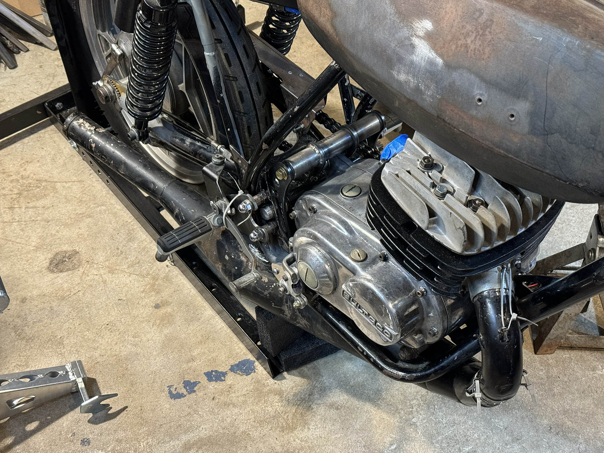
I’m working on the shift linkage, which is (of course) way more complicated than you’d expect—because Bultakenstein. A late Bultaco engine’s shift shaft has spined ends exiting both sides of the crankcase, which sounds fortunate, but (and these are big buts) the left side comes out behind the countershaft sprocket, and the right side is directly above the bottom frame tube. Furthermore, they both have limited clearance around them due to the shape of the crankcase castings, limiting how far the original shift lever can be rotated on the shaft splines. You can re-clock it somewhat, but not drastically. So, routing the transverse shaft that the Yamaha shift linkage will attach to is somewhat problematic. There is no convenient location to mount the self-aligning bearings I bought 3-1/2 years ago for my shift linkage crossover shaft. The former footpeg boxes on the frame would be the most logical point, if not for the fact that the the rear engine mount blocks the space directly between these boxes.
With the engine and rearset linkage installed, I played around with the cross-shaft position and decided its best location was immediately forward of the old footpeg boxes, as close to them as possible. If I could have thought far enough ahead, I would’ve integrated shift shaft mounts into the rear engine bracket assembly. But that ship has sailed. The current best approach is adding a small plate bolted to the box each side and extending forward far enough to mount the bearing flange in the correct position.
Further complicating the clearance issues, the sides of the engine mount assembly are almost flush the frame, with no clearance for any sort of fastener inside the frame. Also, there is a metal reinforcing rod welded into the center of the footpeg box cavity.
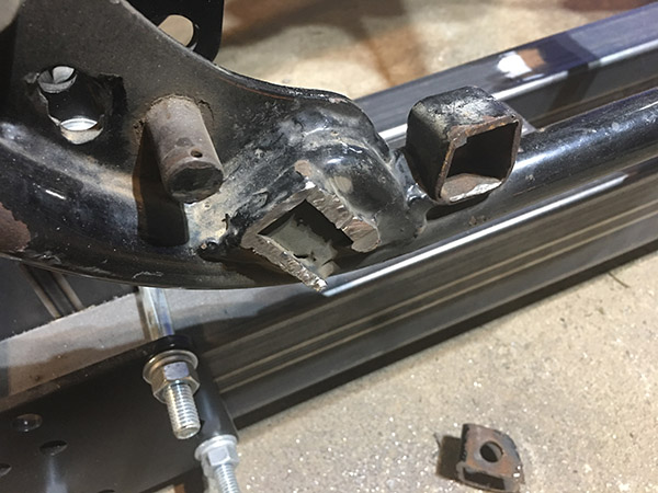
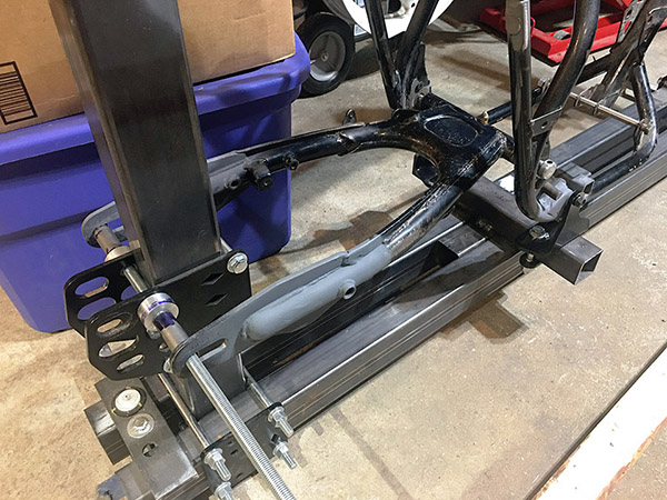
What I did have as a starting point were holes that I’d previously drilled in the forward end of the footpeg mounts. Back when I was calculating the swingarm and rear tire alignment, I’d cut off the old footpeg brackets and drilled those holes to temporarily fix the frame in the jig, as seen on the right side of this photo:
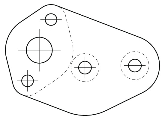
So, I sketched up a 2D plate design that will bolt to the exiting hole, and one more toward the rear of the box.
Thus, what I really needed was a couple of blind rivnuts on each side. This is an ideal application for rivnuts because there will be negligible torsional or tensile stress, just side loads. So, I bought a rivnut setter and a selection of rivnuts off Amazon for $45. The two holes turned out to be the precise diameter needed for the M6 rivnuts that came with my setting tool. I’ve mounted one in the existing hole in each side.
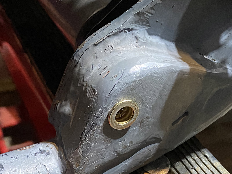
[Also, a good close-up of how grody the junkyard Pursang frame really is.]
I was fearful these would be somewhat weak or rinky-dink. But these are impressive, really in there solidly, and setting them couldn’t have been easier or more idiot-proof. I’ll make up the plates next, then drill the second mounting hole once I have the bearing plates attached and I’m assured of the alignment.