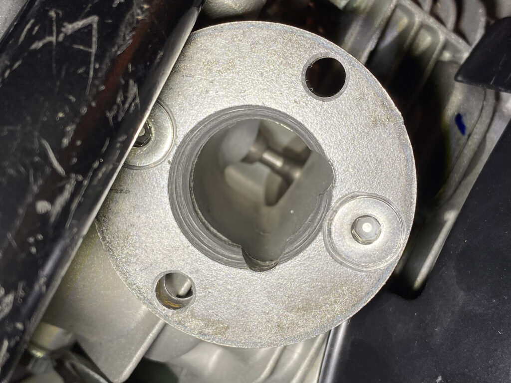
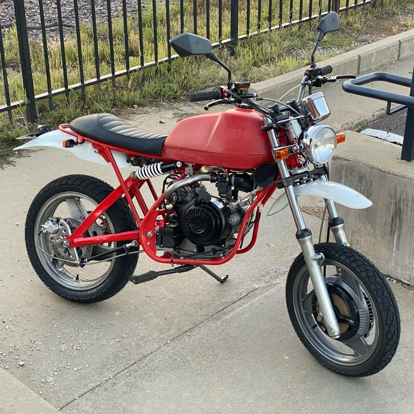
I made a new adapter plate to go between the cylinder head and the intake tract.
My version of this adapter is conceptually similar to one that I made previously for my Honda CL125S:
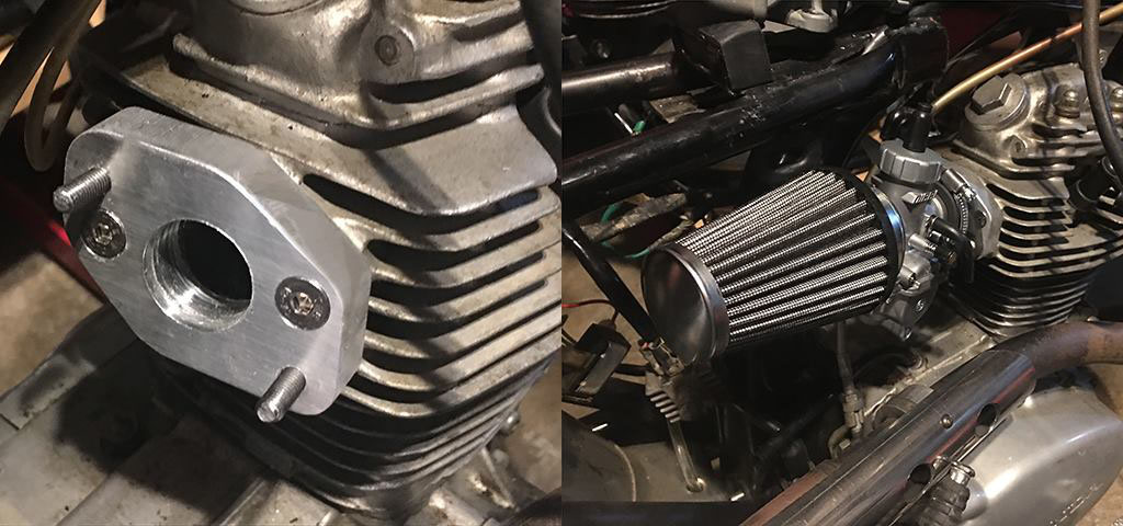
While not absolutely necessary, this doohickey has some advantages:
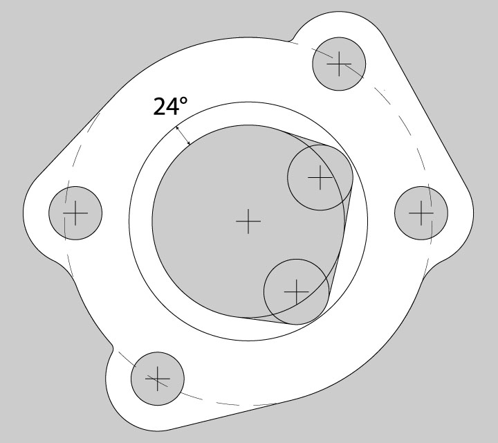
- The engine’s intake port is an odd D-shape, so an adapter flange is needed to smoothly transition it to round. My adapter will be thicker than the anodized one on there now (1/2″ alloy) so the transition in shape of the interior hole will be less abrupt.
- It will have countersunk holes to mount to the intake, like above, and a second set of studs clocked to resolve the frame interference issue I identified previously.
- The intake pipe mounting studs I’m adding will be slightly farther between centers. One of my problems welding was that there was very little clearance between the 1.25″ tube and the bolt holes in the flange plate, so there was precious little room for the weld bead.
- The interior dia. can be matched to the I.D. of readily available 1.25″ dia. 18ga tube.
- The new studs will also be centered on the intake tube. The existing holes are offset slightly. This will simplify construction of the components.
My original design was a fairly complicated shape that I would have three equidistant points at 120 degrees, for mounting in my 3-jaw chuck to cut the taper in the center hole.
When I actually fabricated the adapter plate, I was able to simplify it a great deal by simply using a pre-cut 2-1/4″ dia. x 3/8″ thick steel disk.
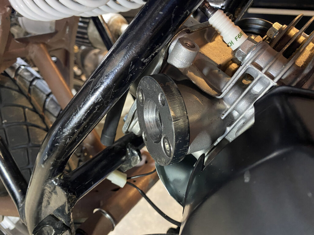
I originally planned to thread the flange mounting holes, but at the last minute I simply drilled 6.5mm holes and will put nuts behind the plate. Unfortunately, I happened to position the lower hole right in front of a cast fin on the head, which will need to be filed back a small amount. I also need to soften the transitions between the main center hole and the smaller “D” holes. In fact, the whole inner surface could use some smoothing; my boring bit was a bit duller than I thought it was.
