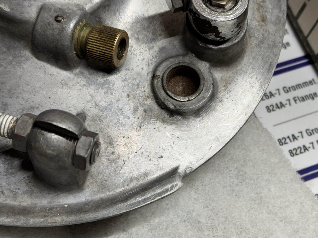
I was able to send a couple of hours in the shop working on the Benelli. I started by checking off one minor task, filing and dressing the brake drum. As regular readers will recall, I cracked off one end of the cast outer flange during the rather arduous disassembly. I got out the Dremel and emery cloth and did my best to hide my crime.
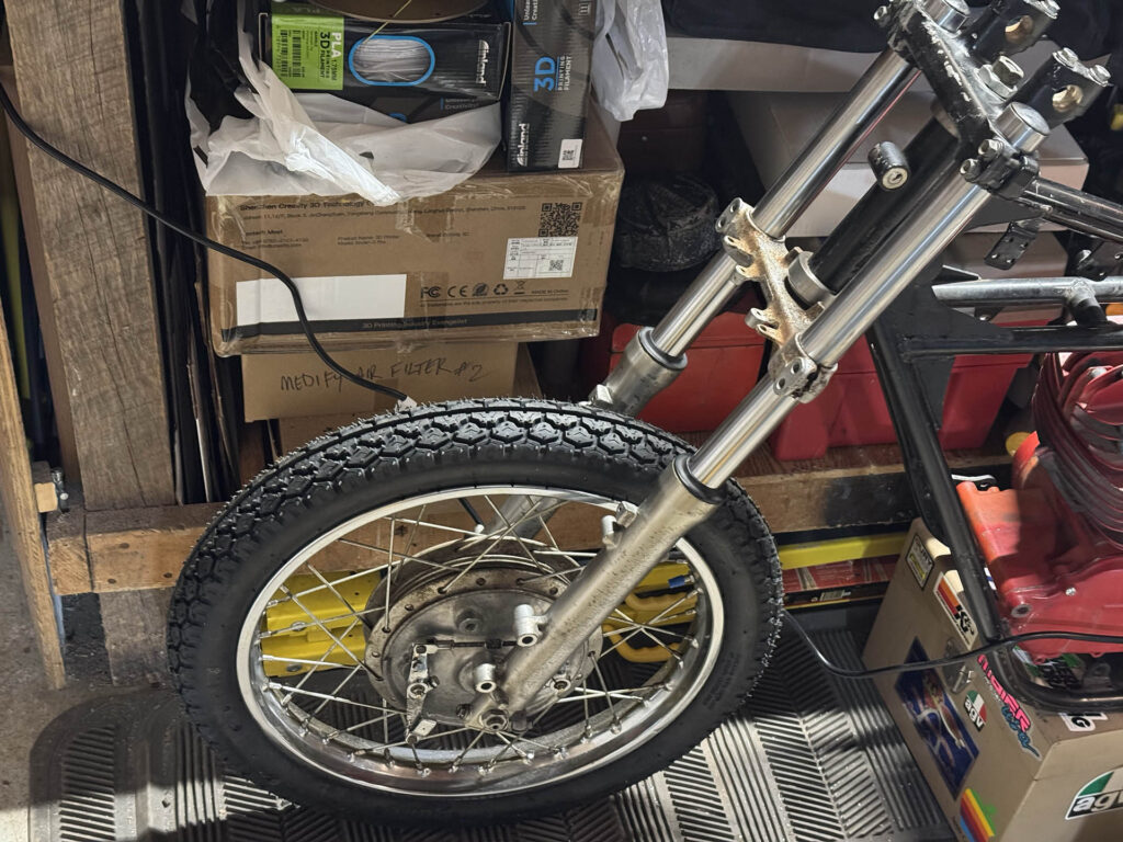
I then moved on to the significantly more daunting task of installing the front end. The first step was to carefully tap the Moto Guzzi bearing adapter cups into the head tube on the frame.
Installing the XR200R steering yokes required somewhat odd-sized TR35 (36mm ID x 52mm OD) tapered roller bearings, which I had to order from Pyramid Parts in the UK. I discovered more a year ago that the XR200R steering stem I chose is too short to fit the Benelli frame, once the adapter cups were installed. That meant machining a replacement, right? Actually, no. There’s an easier alternative: two separate bearing surfaces.
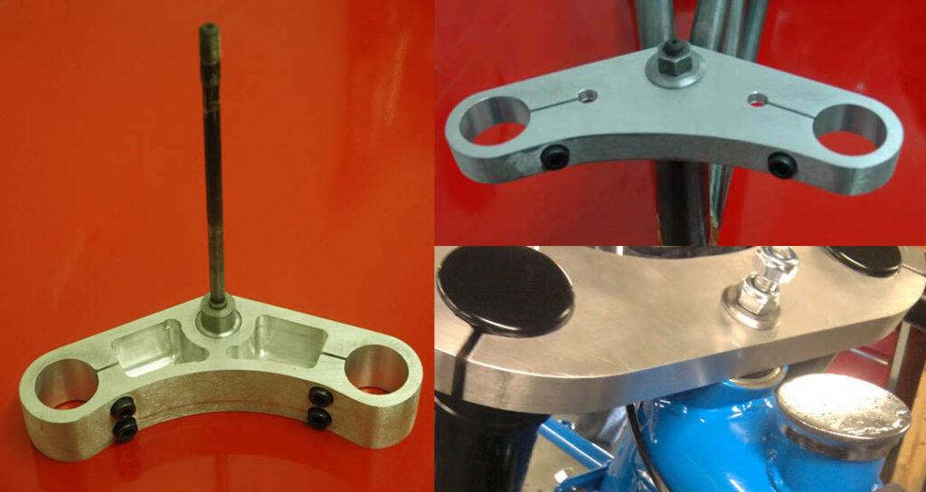
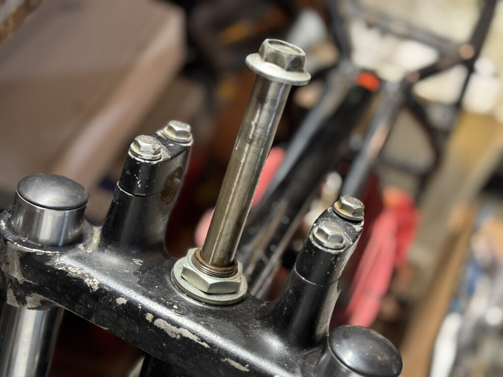
Using a threaded rod to connect the steering yokes sounds sketchy, but it is sound engineering and more common that you might think. Many race fabricators including the esteemed Tony Foale have used the technique. You just need a bobbin that engages with the yokes at the top and bottom and positively locates the bearings. The rod in between them has no side loads; it’s just there to set the bearing preload. Once the forks are installed and the pinch bolts tightened, they transmit the loads to the bearings and do much of the work of maintaining the proper yoke spacing. Here’s a couple of photos I’ve cribbed from Tony Foale’s site showing how he does it. You can see that just a standard hex nut protrudes through the top yoke.
I intended to follow suit and machine two bobbins. But then I realized that I already had two properly machined bearing surfaces on the existing stem. Since it was hollow, I could just cut it in two and thread the ID for a large-diameter tube. Oh wait—due purely to circumstance and dumb luck, it got even easier. I happened to find among my spare parts a front wheel axle the exact diameter needed for a snug slip fit within the steering stem. When I say the insertion was snug, it required a bit of oil to smoothly insert all the way. If I held my thumb over the bottom of the stem, it created an air seal that kept the rod suspended. By my rough calculations, it would be just long enough to work.
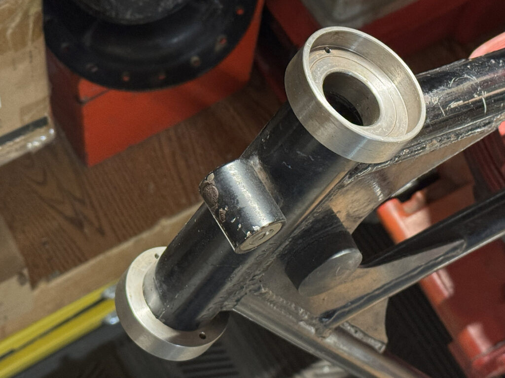
There was nothing left to do but chop the steering stem in half. A few minutes with a cut-off wheel and a bit of clean-up on the belt sander and we’re ready for assembly. Zero thread cutting required! Here it is, showing the cut with the new bottom bearing pressed into place. Despite the fact that the inside of the steering stem was not a precision-machined surface, there was no perceptible wobble to the top section.
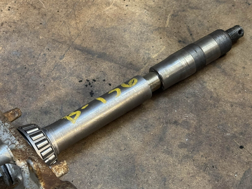
Looking at the stem, the lower of the two threaded sections will go unused. The large nut that goes on the upper threads will no longer provide preload adjustment; it simply attaches the top half of the stem to the top yoke. It’s hard to tell in the photo, but there’s a slight step in diameter where the lower threads start. The top yoke bottoms out on this lip. I may apply some Loctite 680 between the stem and the top yoke to lock them together, since they can now effectively act as one piece.
And here it is, all bolted up. When I said the axle was barely long enough, that turned out to be very true. In order to fit the bolt to the inner (axle) shaft, I had chuck the upper section of stem in the lathe and remove about 1/4″ of the threaded portion, which extended beyond the stem nut and was now unneeded. Even with that, the thick axle nut doesn’t fully engage the axle threads. The proper solution is to turn down the diameter of nut on one end, so that there’s a flange. That would allow the nut to drop down inside the stem tube slightly. I might go all-out and get for a domed cap nut to do that surgery on.
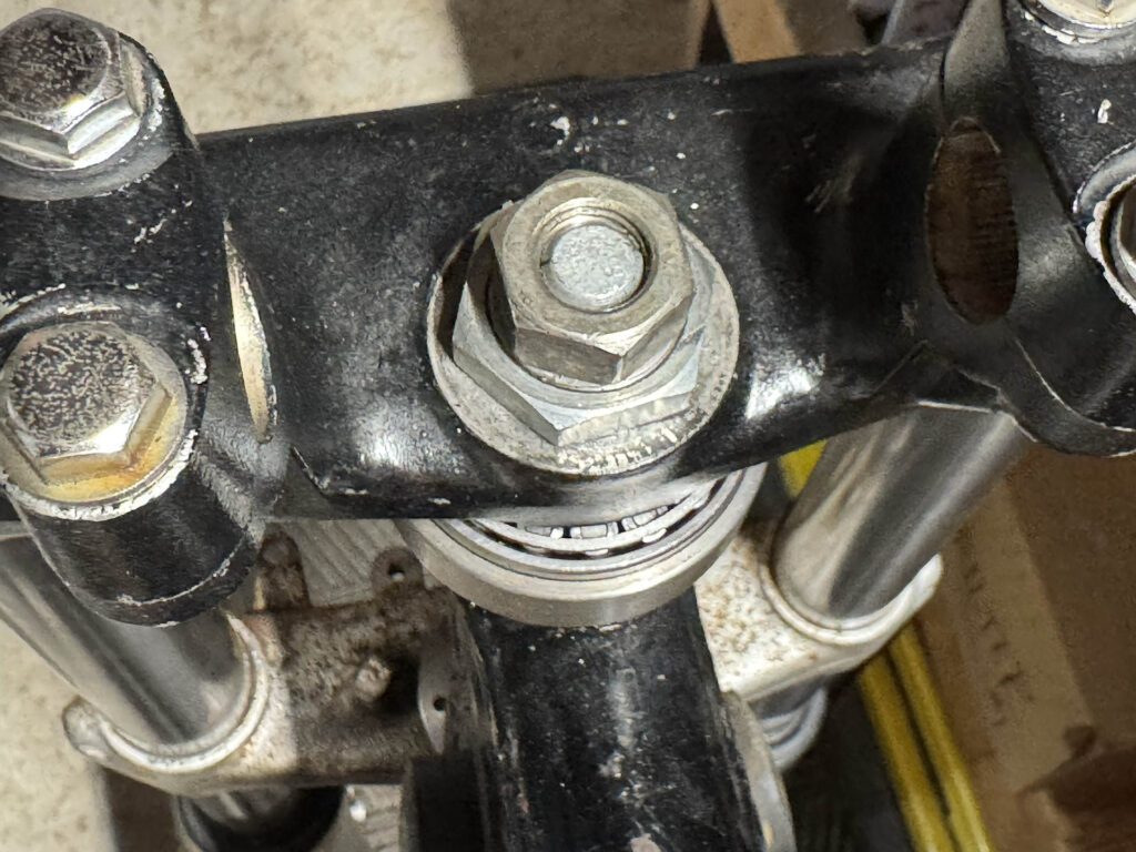
Looking at the photo, one slight issue is apparent. The top bearing is completely exposed to whatever liquid or crud might get in there. Note that I didn’t put the typical rubber sealing disk under the bearings. This was partially to keep the top-to-bottom distance as short and possible, but mostly because I didn’t have any in good condition. I’ve omitted this seal under the bottom bearing on other bikes; as long as you’re not riding in winter slop and periodically clean and re-grease the bearing, it will survive just fine. But unlike the bottom bearing, gravity is working against you on the upper, so I’ll eventually have to get a seal to sit on top of the upper bearing. That will be easy enough to fit later, and is only a $7 part.
It’s not perfect, but I’m really happy with this. Even though it’s just going to be a non-running display bike, I didn’t do anything truly bodge-y or nonfunctional. The next steps are fabricating steering stops and finding fork gaters for a more old-timey appearance.