I went ahead and shifted the swingarm closer to the centerline of the bike.
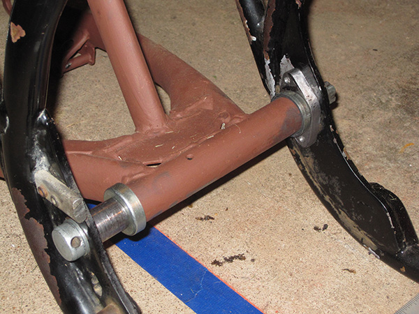
I created a spacer for the left side of the swingarm from 3/8″ steel plate. Not only did I want a more symmetrical appearance, but I also wanted that end of the pivot bolt to bear on a more solid point in the frame. Initially, it was positively located only by the 1/8″ thick escutcheon plate on the outside of the frame. Not it sits in a much more robust fixture. As a bonus, the two allen fixing screws thread into metal over their entire length now.
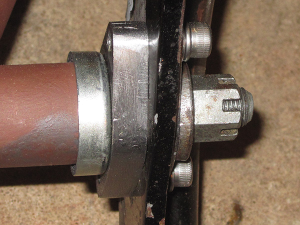
I created this by hand using a hack saw, file, and a drill press.
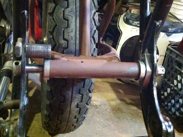
One thing always leads to another, and in this case adding the spacer inside the frame meant I needed to have the step between the two pivot bolt diameters shifted to the right the same amount to create clearance for the swingarm to slide over farther on the pivot bolt. Fortunately, a friend of mine turned it on his home lathe for free.
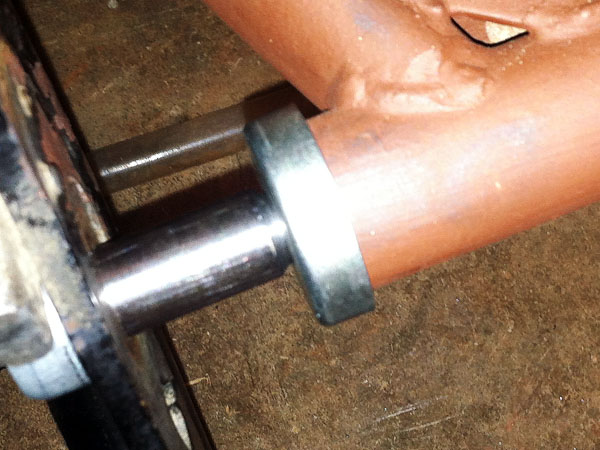
Here, I was test fitting it without the the spacer collar after the pivot was re-machined, and you can see the filleted step down.
At the same time, I verified the amount I needed to shorten the spacer, then carefully cut it with a hacksaw and filed the end square.
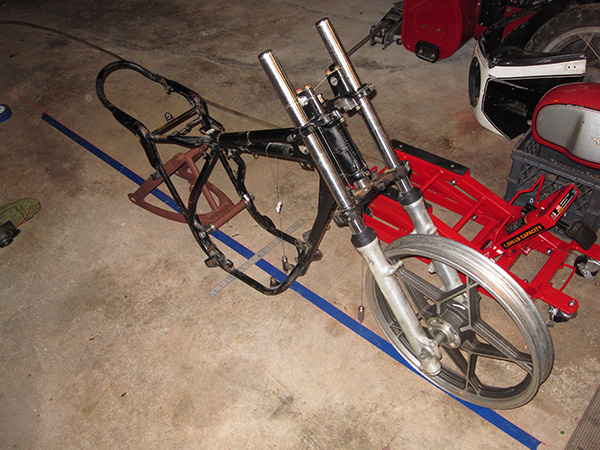
Once I had the swingarm re-installed securely, I slipped the front end back on and started figuring out exactly where my rear wheel needs to be positioned. I marked a chalk line on the concrete floor and then carefully ran some blue painter’s tape along the mark. I then used a laser level and some plumb bobs to determine the the centerline of the bike and position it as precisely as possible over that line. Some further measuring verified that the frame tubes under the engine are, indeed, symmetrical and the two swingarm mounting plates in the frame are the same distance from the C/L on both sides. I had suspected this all along, but I didn’t dare simply assume it.
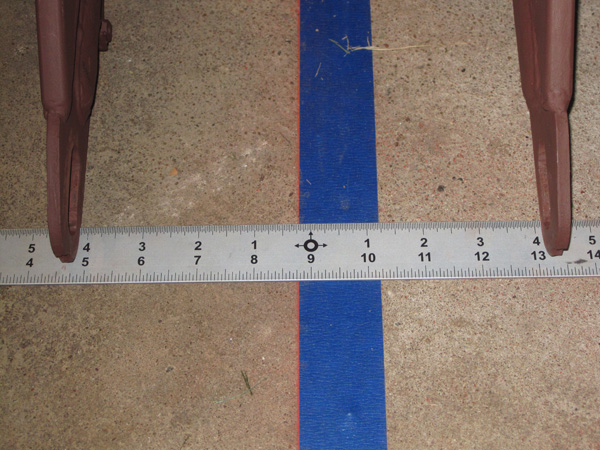
Ultimately, I moved the rear wheel (well, technically the midpoint between the rear wheel mounts) from around 7mm to the left of center originally to now around 2 – 3 mm to the right.
My measuring techniques are not the most precise, but I’m confident enough I will get things aligned close enough to true not to be detectable to the rider.
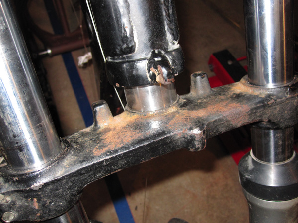
Another task I need to tackle on the front end is fabricating steering stops. Here you can see that the Bultaco had the frame stop at the front of the steering head, whereas the Suzuki triple clamps has stops designed to contact the frame below and to the rear of the head tube.
There are plenty of possible solutions, but I’m trying to figure out an elegant arrangement that will be attractive and solid, yet not terribly expensive or difficult to fabricate with low-tech tools.