The Pursang frame is definitely not an optimal candidate for a monoshock. The problem is not interference from the engine (as Ken pointed out, there’s plenty of room between the cylinder head and the tank). The issue isn’t anything terribly fundamental with the frame itself, just a circumstantial quirk — the two downtubes running from the backbone to the swingarm pivot area are not splayed very widely.
So unfortunately, when trying to install a monoshock damper unit horizontally, the diameter (of the spring, for the most part) is too wide to fit between the frame where the tubes come together.
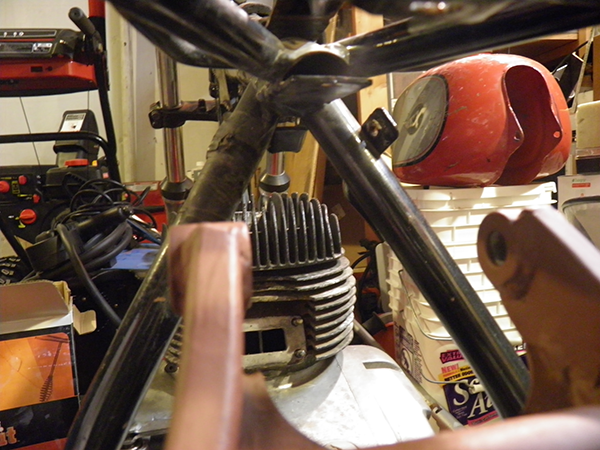
I’ll demonstrate with an old Honda XR100 damper. This isn’t what I’ll use, but it was a dirt cheap starting point and it represents pretty much a “best case” scenario. It’s only about 10.5″ long, it has a narrower diameter than most, and the spring only covers about 2/3rds its length.
If I position it up high in the frame triangle as shown, near the backbone tube, I can only fit the part that extends beyond the spring between the tubes, and I end up with the rear of the shock here:
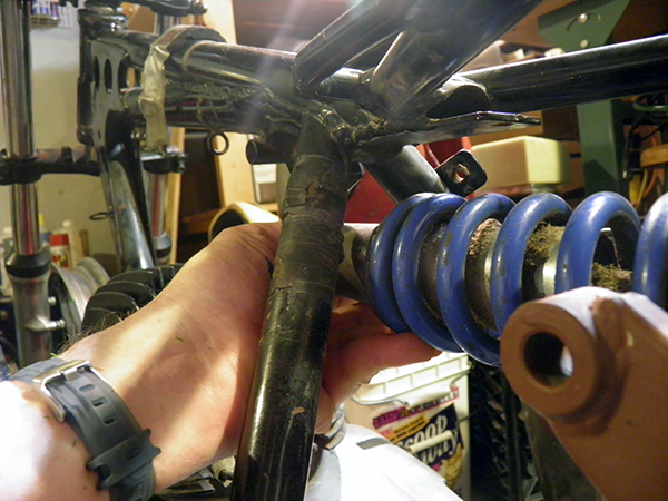
So I worked the other way. If I start by attaching the rear of the damper to the swingarm, the damper must angle down enough for the the spring to fit between the frame, and…oops!…the front of it ends up somewhere in the middle of the carb. Even if I could get it to fit, the front would be mounted so much closer to the swingarm pivot than the rear that the compression rate would dramatically decrease as the damper compressed.
Since there’s no way I’m about to attempt modifying the frame loops, my shock location ends up something like this:
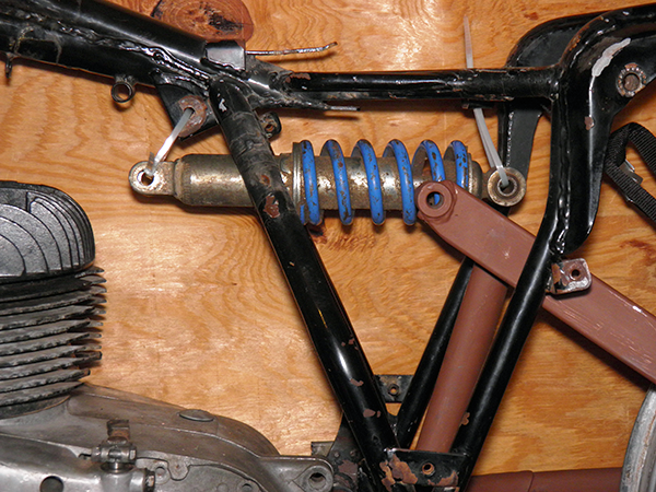
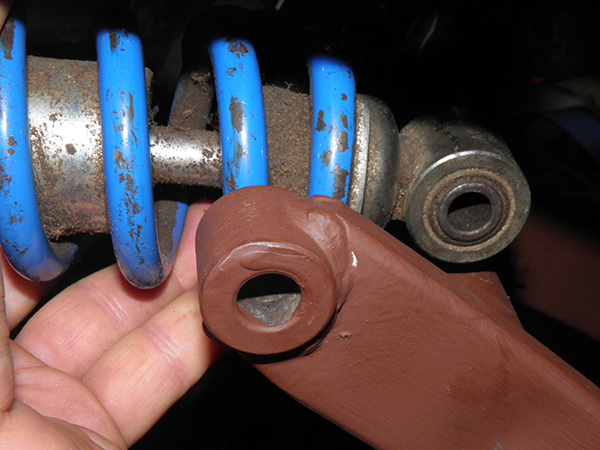
This isn’t really so bad an option. It works aesthetically, and I have plenty of room for the rear cylinder head stay, carb body, air cleaner, throttle cable, etc. I just need to find a way to attach the rear of the shock to the swingarm.
My first idea was the most basic conclusion: a linkage on either side of the shock, like dogbones, that run from each side of the rear shock eye forward to the mounting holes in the swingarm. But I quickly realized there’d be too many hinges in the chain. The only thing keeping the rear damper aligned with the suspension forces would be the weight of the bike keeping the dogbones from swinging in their arc. I pictured the rear shock links camming over as I went over a bump and jamming the shock against the underside of the seat. Yea, that wasn’t going to work.
So I briefly played with the idea of some sort of horseshoe-shaped bracket that wrapped around the back of the damper, bolted to the kind of rebuildable damper that has a threaded stud on one end, so it couldn’t pivot:
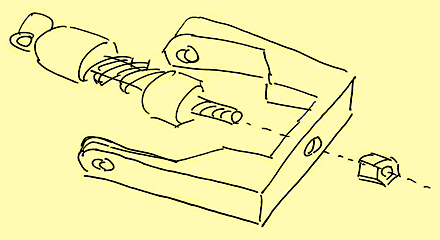
Forgive the crappy 10 second pencil sketch, but that’s as far as I needed to journey down this path before realizing what a horrifically bad idea this was: same rotational stresses on the shock, but now they get concentrated as bending forces on a single stud. Ummmm, no. If the damper unit extends past the swingarm mounting pivot, I have to control the forces along the other axes with something other than the damper itself. That led to thinking about a bracket that attached solidly to the swingarm, but that would require some other mounting point in addition to the existing damper pivots, and none of the other swingarm tubes seemed properly designed to deal with that sort of stress.
So, what if I located the rear damper eye not in relation to the swingarm, but to the frame? The swingarm moves in an arc, so it would require a second set of linkages. What would that look like?
Fortunately, my third time back to the drawing board was more promising…
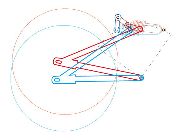
Bingo! Now we’re getting somewhere!
The uppermost pivot point in the diagram is what’s mounted to the frame, perhaps to an additional frame tube welded between the old shock mounting points. There’s already an existing crossbar just ahead of that, but I will probably add something more. Even though it only has to deal with a fraction of the suspension forces, I think adding some additional reenforcement would be in order. Considering that the old twin shocks funneled 100% of the suspension stress to those points, those have got to be pretty safe points to start with.
Not only does this design allow the damper to extend past the mounting points, but this arrangement has the very real advantage of (at least theoretically at this point) being configurable for a (mildly) progressive rising-rate suspension. Space constraints and the length of whatever damper unit I end up with will probably limit how much I can play with the length of the linkage arms, but at the very least I should be able to keep the compression rate virtually flat, as it is in the photo.
By golly, this might just work better than I’d originally planned.